I’ve been writing about display technology for more than 30 years now—going all the way back to slide projectors and cathode ray tube (CRT) projectors in the late 1980s. Back then, we saw new and exciting ways to create images on an almost annual basis: Liquid crystal-display (LCD) projection panels, LCD projectors, plasma display panels, light-valve projectors, LCDs, liquid crystal on silicon (LCoS), laser CRTs, light-emitting diodes (LEDs), organic light-emitting diodes (OLEDs), and the list goes on.
Those were heady times. The advancements came so fast and furious that they spawned (a) an incredible number of acronyms and (b) endless confusion among potential customers. Back then, even some marketing and sales folks didn’t fully understand how their display products actually worked.
From Luxury To Commodity
Over time, the torrent of new display gadgets slowed to a trickle. As more manufacturers jumped into the fray, prices began to drop. Display manufacturing began to shift away from North America, Europe and Japan and toward South Korea and China. Price declines accelerated as what once were expensive purchases with long operational lifetimes devolved into mere commodities.
Consider the fact that, at my very first InfoComm Projection Shoot-Out back in 1994, a state-of-the-art LCD projector, from a first-tier brand, featured VGA (640×480) resolution, had all-analog inputs, could crank out about 500 lumens (often with poor uniformity), weighed between 25lb. and 30lb., and had a retail price tag of about $8,000 to $10,000. Some 25 years later, you can walk into your local Staples store and pick up (or, more likely, arrange to have shipped) a 5.5lb. projector with 3,000 lumens of very uniform brightness and WXGA (1280×800) resolution for less than $500. That’s essentially a fully depreciated expense item after one year. You could also stroll into your local Best Buy and purchase a 55-inch ultra-HD LCD TV, boasting high dynamic range (HDR) support, for about the same price.
Understanding Fundamentals
The fact is, displays are cheap and offer amazing performance for the cost. Many readers might not remember the epic 3LCD versus Digital Light Processing (DLP) business-projector battles from the late 1990s, and others might have forgotten that rear-projection monitors and televisions were very viable products until falling LCD-panel prices killed them off. (I would bet many readers have faint memories of the aforementioned Projection Shoot-Outs and the inevitable controversies they spawned every year with regard to measuring color lumens, American National Standards Institute (ANSI) contrast, native imaging resolutions and so on.)
Today, we don’t stop to think much, if at all, about exactly how those electronic images wind up on large, self-contained display screens in movie theaters, on stadium billboards, on our smartphones and even on our watches. Instead, we just plunk down some cash with the confident expectation that all these wonderful toys will just work. But, being of the “old school” that teaches you first to learn about what’s under the hood before you buy the car, the Editor and I agreed it was way past time to publish a tutorial on current display technologies—at least, the flavors to which our industry most frequently turns.
So, let’s take a dive behind the glass and the lenses to see how all this magic happens!
Liquid Crystal Displays (LCDs)
LCDs are, by far, the most common of all displays. They come in a wide variety of sizes, and they’re used in both projectors and direct-view displays. Regardless of size, all LCD-imaging pixels work on the same principle: Tiny liquid crystals in suspension respond to varying electric charges to “twist” into different alignments. When they do that, they can pass or block light rays—a phenomenon known as birefringence.
LCD Stack Architecture
Displays made out of liquid-crystal panels have several layers to them. As it turns out, the source light has to be polarized so that it can be shuttered completely. That means that a panel composed of LCD pixels requires a backlight source (originally, fluorescent lamps; now, LEDs), a polarizing filter, the LCD pixel array with individual switching thin-film transistors (TFTs), a color filter array and another polarizer, plus the front glass. The actual liquid-crystal compounds come in a paste that fills each pixel cell and is manufactured by a handful of companies—no table among them, Merck KGaA in Germany.
Unfortunately, LCDs are not very efficient. Believe it or not, only about five percent of the photons generated by the backlight make it all the way through the LCD array to your eyeballs. That also holds true for LCDs that use HDR illumination, either from dense clusters of local-area “mini” white LEDs, or from HDR enhancers like quantum dot films and layers. However, they are inexpensive to manufacture in large sheets, which are known as “motherglass.”
Just as you make brownies by filling a pan with cake mix and then slicing up the finished product into smaller sizes, LCD motherglass is cut into smaller panels to be incorporated into televisions and monitors. The size of the motherglass is optimized for the number of glass cuts. A large motherglass size, used to cut 55-inch-and-larger panels, is approximately 10’x9′ and all of about 0.02 inches thick. Gen 10.5 fabs now running in China can produce eight 65-inch panels or six 75-inch panels from motherglass measuring 11’x9.6′.
The Scalability Of LCDs
David Barnes, a longtime display-industry analyst, used to say, “With LCD, the pixels are free.” By that, he meant that scaling up in resolution from full HD (1920×1080) to ultra HD (3840×2160)— even to 8K (7680×4320)—is a relatively simple job using LCD technology. That’s why LCD-panel manufacturers are moving away from full HD and toward ultra-HD panels, and they’re even introducing 8K glass cuts. There’s little return on investment (ROI) in manufacturing LCD panels these days, and it’s a very expensive proposition to build a large fab that might never return a profit.
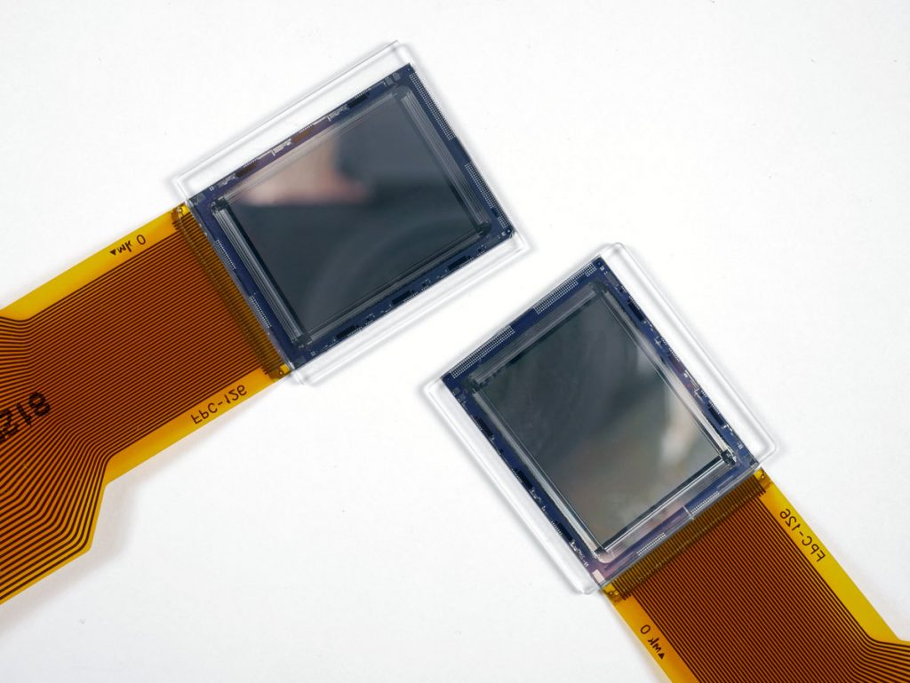
LCDs are also manufactured in very small sizes on wafers and cut apart to be used in projectors. Unlike the amorphous silicon (aSi) and low-temperature polysilicon (LTPS) processes used to form the tiny control transistors on each LCD pixel in a television, these tiny LCD chips employ high-temperature polysilicon (HTPS) processes. Seiko Epson Corp. in Japan manufactures most of the HTPS LCD chips in projectors.
LCD Projectors
In a 3LCD projector, three monochromatic HTPS panels are coupled to individual red, green and blue dichroic color filter and bonded to an integrating prism in precise registration. The three images then combine to produce full-color images at the lens. There is no loss in color quality when increasing brightness; full color saturation can be maintained at any brightness level.
Every LCD projector you see, regardless of the light source, uses this three-panel RGB imaging engine. It is possible to achieve 4K (4096×2160) resolution with 3LCD, although, to this author’s knowledge, no projectors currently offer it. Both large and small LCD panels are transmissive imaging technologies— that is, light passes from the illumination source in one direction: through the light shutter and into your eyes.
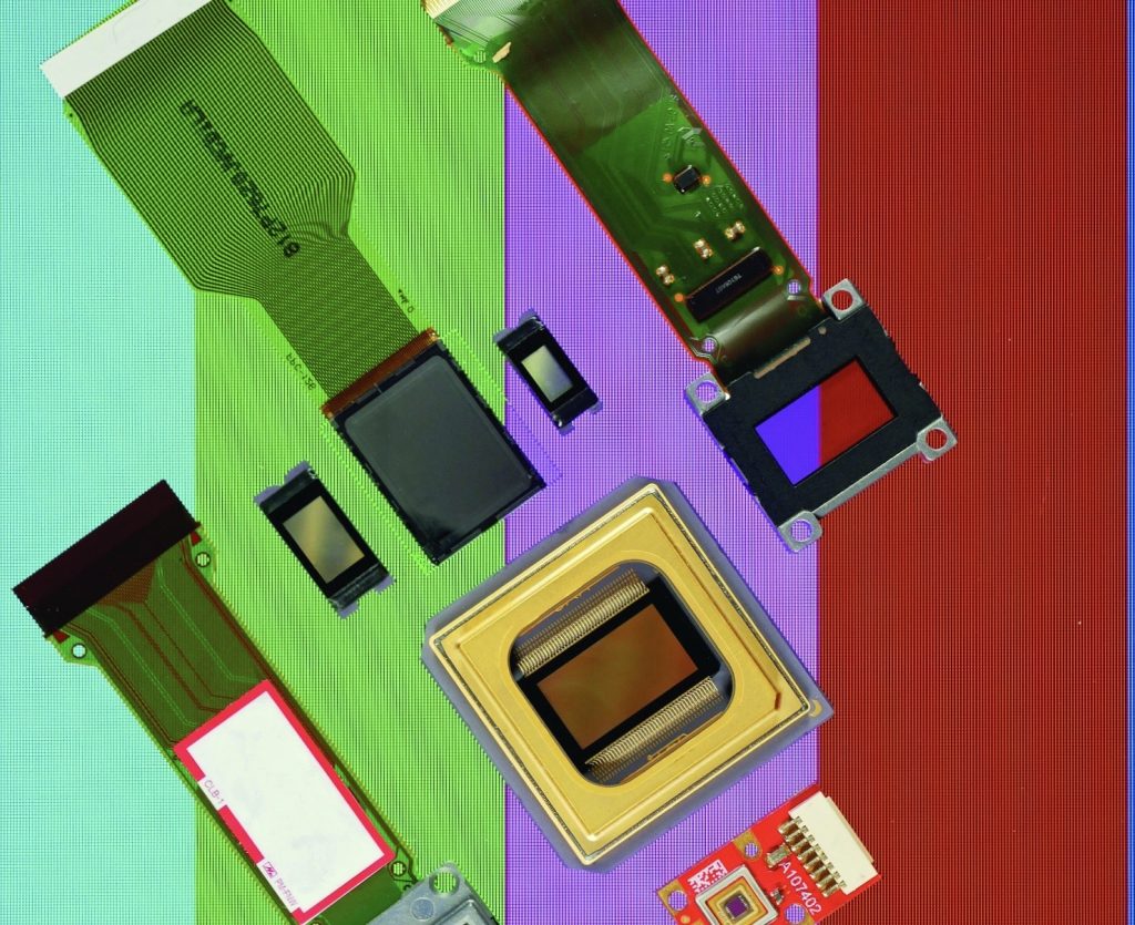
Digital Light Processing (DLP)
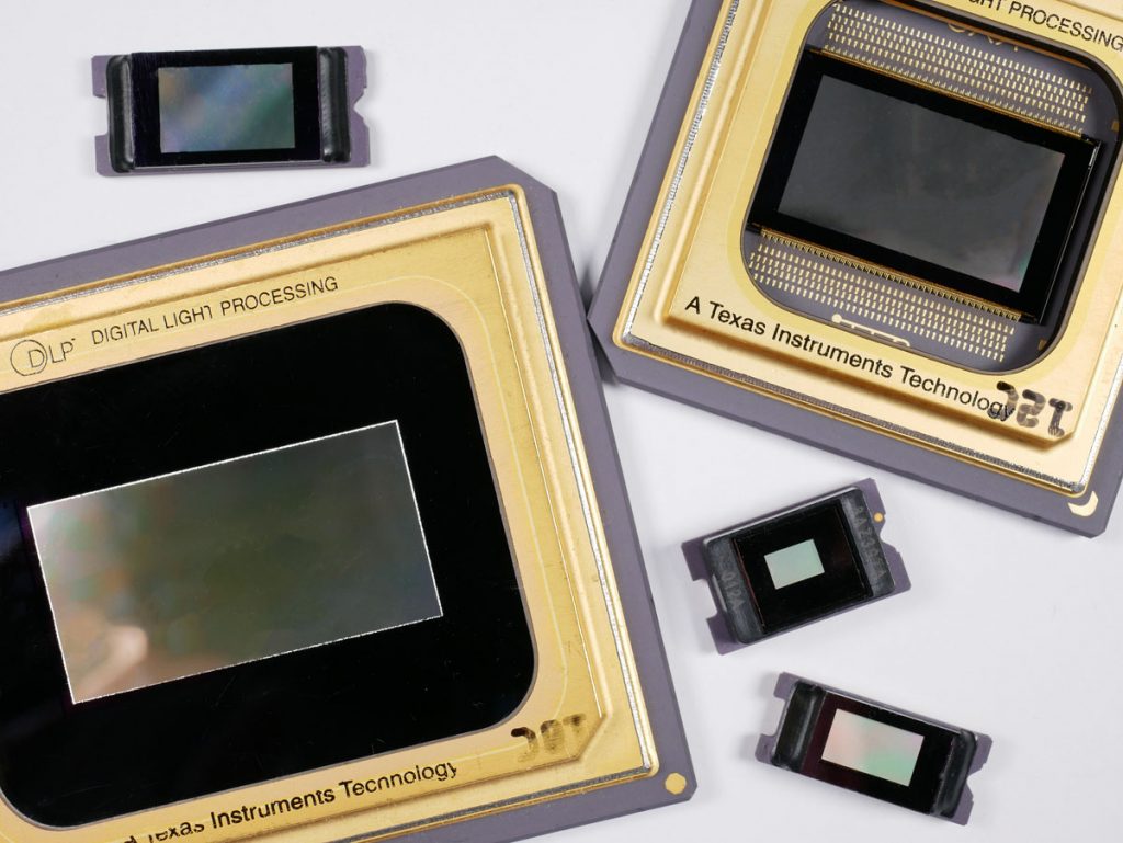
Texas Instruments originally developed DLP in the mid-1980s as a way to create images in printers. Although that didn’t quite work out, an alternate use—an imaging device for projectors— took off like a rocket. Today, DLP is the imaging technology used in a majority of movie theaters, not to mention in business and home-theater projectors. It was also the core technology for several lines of rear-projection televisions before large, cheap LCD TVs killed off that product category. Unlike LCD technology, DLP is a reflective imaging system.
The Fundamentals Of DLP Technology
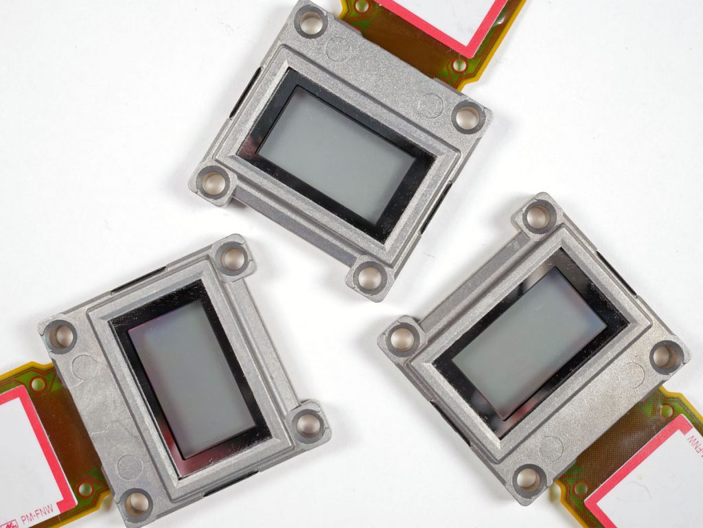
The heart of DLP technology is the digital micromirror device: a complex semiconductor that has thousands of tiny mirrors (pixels). Each mirror rapidly tilts back and forth from an “off” state to an “on” state and back again; the maximum tilt angle is about 12 degrees. The technique couldn’t be simpler: When a pixel is “on,” light from a high-intensity laser-phosphor engine is reflected toward a lens and onto a screen. When a pixel is “off,” the light is reflected into a light-absorbing surface that doubles as a heat sink. DLP is classified as a reflective imaging technology because light must travel in two directions to get to your eyes.
You might be thinking to yourself, “How the heck do you get grayscale images out of that?” A technique known as pulse-width modulation (PWM) gets the job done. Because your eye doesn’t perceive flicker above a certain speed (around 80Hz, for most people), and because your visual response has a slower rise and fall time than a digital micromirror device (DMD) does, we can use this digital technique to create different luminance levels. If the number of “on” cycles in a given time interval is 75 percent and “off” cycles represent 25 percent, that appears to our eyes as a 75-percent luminance value. If we reverse those ratios, we have a 25-percent luminance value. Pretty cool, right? (Plasma displays and TVs worked the same way.)
Introducing Color
At this point, all we have is a monochromatic (black-and-white) light modulator that produces grayscale images. To get full-color images, we have two options: The first is to add a spinning color wheel with red, green and blue segments (and sometimes yellow and white) and synchronize it to a solo DMD. This single-chip design was, and remains, the basis for all small-business and home-theater DLP projectors. If it suffers from a drawback, it’s that the use of a white segment sacrifices some color saturation to achieve higher brightness. The second option, which is used in installation, large-venue and cinema projectors, is to incorporate three distinct DMDs into a polarizing beam splitter (PBS) with discrete red, green and blue color filters to achieve high-brightness images with fully saturated colors.
The three-imager-with-combining-prism approach takes up a lot more room, but it creates the most accurate images. Moreover, it can work with any light source, like HTPS LCD panels. The preferred source these days is laser phosphor, wherein light from a blue laser array strikes a yellow-green color wheel to produce white light. Precision dichroic filters subsequently refract that light into red, green and blue components.
DLP Compared To LCD
For many years, there were running arguments between the 3LCD and DLP camps about durability, projector life, color accuracy and so on. Of course, neither camp was paying attention to the development of larger and cheaper LCD panels with higher resolutions; eventually, those put a big crimp in projector sales. Today, both camps are relatively quiet and single-chip DLP projectors are priced comparably with equivalent-brightness LCD projectors.
DLP projectors are made with full-HD chips, cinema 2K chips and even native-4K (4096×2160) chips. Other DMD resolutions have been used to get to 4K and even 8K by rapidly shifting pixels. We don’t perceive the flicker or shift—just a high-resolution, full-color image. (This technique has also been used by LCoS projector manufacturers.)
Liquid Crystal On Silicon (LCoS)
LCoS technology has been around for a long time, and it has popped up on occasion as an alternative way to get higher resolutions from projectors. LCoS panels are manufactured in much the same way that HTPS LCDs are, but with a difference: The device backplane is a mirrored surface, so light from a lamp or laser-phosphor engine enters the chip from the front, is twisted and exits at a different angle (about 90 degrees). Quite the neat trick! It’s kind of like having cars drive through a single tunnel in both directions by putting half the traffic on the ceiling or on the walls!
A Rare Technology
Numerous companies over the years have tinkered with LCoS—and it spelled the demise of many of them—but very few manufacturers play in this space nowadays. Notable exceptions include Sony, with its Silicon X-tal Reflective Display (SXRD) LCoS chips finding their way into cinema and high-end home theater projectors; JVC, with its Digital Direct Drive Image Light Amplifier (D-ILA) LCoS home-theater projectors; and Canon, with its line of high-resolution business and post-production projectors that have LCoS chips.
The Mechanism Of LCoS
The light-engine schematic for an LCoS projector with three chips (RGB) is about as complex as the piping diagram for a liquid oxygen plant, and it requires very close tolerances so that colors are not out of registration. Some cinema purists prefer LCoS to DLP for both post-production work and home-theater viewing because it produces images that look more like film grain. LCoS, like HTPS LCD and DLP, plays well with laser-phosphor light engines, too. Note that it is only a projection technology, but it has an analog response like HTPS LCD. Like DLP, LCoS imaging is a reflective display technology.
Light-Emitting Diodes (LEDs)
I should clarify in this section that we will be discussing two different classes of LEDs. The first involves inorganic LEDs (iLEDs)—the kind you commonly see on signs in stadiums, in Times Square, along the famous Strip in Las Vegas NV and, increasingly, in staging applications. The second involves OLEDs, which are very different beasts. Those are finding their way into high-end televisions, smartphones, tablets, some laptop screens and, now, displays for commercial AV.
iLEDs
iLEDs have been with us for a long time (see “The Mouse That Roared” in the October 2019 issue of Sound & Communications), but it’s only in the past 25 years that they have been usable in practical, full-color displays. That’s because blue LEDs were inefficient and very expensive to manufacture until 1994, when Shuji Nakamura of Nichia Corp. developed the first practical, scalable manufacturing process for blue LEDs using gallium nitride. A practical green-LED design followed soon after. (Nakamura and his colleagues eventually won the Nobel Prize in 2014 for the discovery.)
iLEDs couldn’t be any simpler in design: A voltage is applied to the anode of a simple semiconductor junction. As electrons flow through the junction (again, usually gallium nitride), photons are emitted through a small lens. And those photons are plenty bright! An individual LED tile can emit as many as 2,000cd/m2 of light energy, as well as corresponding heat that must be dissipated. In this way, LEDs are the Marshall amplifiers of the display industry when compared to other emissive displays!
Luminance-To-Voltage In LEDs
But there’s a catch (as there always is). Although LEDs can be operated in a linear mode, producing increasing amounts of photons as the operating voltage increases, they don’t respond very linearly. If you were to graph the luminance response of an RGB LED set against rising voltages, the gamma curves would look like three drunks wandering across a parking lot. Plus, operation in an “always-on” mode generates quite a bit of heat, and that heat has to go somewhere. “Always on” works OK for indicator lamps, but isn’t the best approach for displays.
To get around that problem, we fall back on the time-tested and proven technique of PWM, as we did with DLP imaging. The good news is that LEDs have a very fast rise time and an almost equally fast fall time, which means we can operate them at very fast speeds in switched mode. (How does 3,000Hz to 5,000Hz sound?) Because we already have full-color operation, all we have to do is set PWM characteristics for each color that are based on luminance levels over time. It obviously works, as you’ve seen if you’ve been to a trade show, a shopping mall or an arena lately.
Individual LED tiles that make up a large display are manufactured using LEDs from the same manufacturing batch to ensure the best color matching. That isn’t quite as critical with outdoor displays, but it’s important for mission-critical imaging and a new vertical market—LED cinema—that’s just now getting off the ground worldwide. As noted in “The Mouse That Roared,” iLEDs can be made in a variety of chip sizes and pixel-pitch combinations, including “micro” and “mini” varieties. The former is a ways off from becoming mainstream, but the latter is finding applications in direct-view displays and as backlights in HDR televisions.
OLEDs
OLEDs are a lower-power version of their inorganic cousins. Numerous companies have been tinkering with OLED technology since the 1960s, but it’s generally agreed that Kodak researchers developed the first practical OLED (white) in the 1980s. Over time, we saw the introduction of yellow, red, light-blue, dark blue, orange and green LEDs, all in small batches and mostly for experimental work.
The Kodak white OLED (which was discovered by mistake, with researchers trying to make a better photocell) was eventually coupled to color filters to produce small emissive displays. I recall seeing demos of those and “pure” RGB OLEDs for many years at CES and Society for Information Display (SID) conferences. In an OLED, voltage is applied to an anode and current flows through a junction made up of an organic compound. As with iLEDs, photons are emitted as current flows. The intensity of those photons, although not as bright as iLEDs are, is pretty strong.
The issue with OLEDs is the same one that cathode-ray-tube and plasma-display manufacturers faced: dark-blue organic compounds—an essential color for imaging—just don’t last as long as red and green compounds do. That’s not a drawback in devices, such as smartphones, that you don’t keep for a long time; however, it’s a potential problem for things like televisions and commercial displays that one should expect to last for many years. To date, no one has really come up with a fix for this differential aging, other than simply to use twice as many blue pixels running at half-power in RGB OLEDs and carefully manage power consumption and peak luminance. (No word yet on white OLED durability, as the “white” comes from a combination of blue and yellow OLED compounds.)
The Commercial Rise Of OLEDs
It took a major manufacturer to make the commercialization of OLEDs happen. LG Display (a subsidiary of LG Electronics) acquired Kodak’s intellectual property on white OLEDs and began to build large display panels with red, green and blue color filters, plus extra white pixels to improve brightness. All the large OLED displays and TVs you see today use panels made in LG’s Paju, South Korea facility. Samsung’s Mobile Display division (SMD) is actively engaged in OLED manufacturing for small screens, as well, using the more traditional RGB OLED design. Sony, Panasonic and AUO in China are also participants in OLED manufacturing.
One advantage that OLED has as compared to LCD is that it can be made with flexible substrates; these can bend, curl and wrap around surfaces. The OLED compounds can also be micro deposited using something resembling an inkjet printer. Although iLEDs have peak luminance levels exceeding 2,000cd/m2, OLEDs can’t operate at those levels. Small-area luminance for a 10-percent white pattern is probably 800cd/m2 to 1,000cd/m2, at best, with full-screen white in the range of 300cd/m2. That does crimp some commercial applications, but it’s more than adequate for televisions, laptops and mobile electronics.
The Wrap-Up
So, there you have it: HTPS LCD, DLP and LCoS for projection displays and LCD, iLEDs and OLEDs for large, self-contained displays. Enough flavors for you? They all have their place in the display universe, and, for now, they’re coexisting (although somewhat uneasily). Many of us display analysts think the ultimate winner will be iLEDs because they can be mass-produced at affordable prices, they have no limits on brightness, they don’t sacrifice color saturation for brightness, they switch at high speeds and, best of all, they are emissive displays that offer very wide viewing angles.
But that day of reckoning is not going to happen anytime soon. Check back with me at the end of this decade….
To read more from Sound & Communications, click here.